

Cleaning Equipment
The equipment for cleaning is shown in the cleaning system flow diagram . The pH of cleaning solutions used with elements can be in the range of 1–13 and therefore, non-corroding materials of construction should be used in the cleaning system.
Cleaning system flow diagram
Suggested Equipment
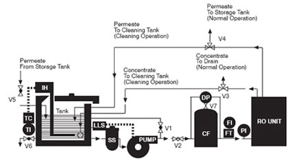
1.The mixing tank should be constructed of polypropylene or fiberglass-reinforced plastic (FRP). The tank should be provided with a removable cover and a temperature gauge. The cleaning procedure is more effective when performed at a warm temperature, and we recommend that the solution be maintained according to the pH and temperature guidelines listed in Table 6.1. We do not recommend using a cleaning temperature below 15°C because of the very slow chemical kinetics at low temperatures. In addition, chemicals such as sodium lauryl sulfate might precipitate at low temperatures. Cooling may also be required in certain geographic regions, so both heating/cooling requirements must be considered during the design. A rule of thumb in sizing a cleaning tank is to use the approximate volume of the empty pressure vessels and then add the volume of the feed and return hoses or pipes. For example, to clean ten 8-inch-diameter pressure vessels with six elements per vessel, the following calculations would apply:
- A. Volume in Vessels
V1 = TT r 2L
=3.14(4 in) 2(20 ft)(7.48gal/ft 3 )/(144in 2 /ft2 )
V1=52 gal/vessael (0.2m 3 )
- Volume in Pipes, assume 50 ft. length total 4" Sch 80 Pipe
Vp = TT r2 L
=3.14(1.91IN)2(50FT)(7.48GAL/FT 3 )/(144in 2 /ft 2 )
= 30 gals (0.11 m 3 )
Vct = V 10 + Vp = 520 + 30 = 550 gal.
Therefore, the cleaning tank should be about 550 gal (2.1 m3).
The cleaning pump should be sized for the flows and pressures given in Table 6.2, making allowances for pressure loss in the piping and across the cartridge filter. The pump should be constructed of 316 SS or nonmetallic composite polyesters.
Appropriate valves, flow meters and pressure gauges should be installed to adequately control the flow. Service lines may be either hard-piped or hoses. In either case, the flow rate should be a moderate 10 ft/s (3 m/s) or less.
Cleaning Elements In Situ
There are six steps in the cleaning of elements:- Make up cleaning solution.
- Low-flow pumping. Pump mixed, preheated cleaning solution to the vessel at conditions of low flow rate (about half of that shown in Table 2) and low pressure to displace the process water. Use only enough pressure to compensate for the pressure drop from feed to concentrate. The pressure should be low enough that essentially no or little permeate is produced. A low pressure minimizes redeposition of dirt on the membrane. Dump the concentrate, as necessary, to prevent dilution of the cleaning solution.
- Recycle. After the process water is displaced, cleaning solution will be present in the concentrate stream. Then recycle the concentrate and permeate to the cleaning solution tank and allow the temperature to stabilize. Measure the pH of the solution and adjust the pH if needed.
Table 1 pH range and temperature limits during cleaning
| Element type | Max Temp 45°C (113°F) pH range | Max Temp 35°C( 95 °F) pH range | pH range Max Temp 25°C (77°F) pH range |
| BW30, BW30LE, LE, XLE, TW30, TW30HP, NF90 | 1 - 10.5 | 1 - 12 | 1 - 13 |
| SW30HR, SW30HR LE, SW30XLE, SW30 | 1 - 10.5 | 1 - 12 | 1 - 13 |
| NF200, NF270 | 3 - 10 | 1 - 11 | 1 - 12 |
| SR90 | 3 - 10 | 1 - 11 | 1 - 12 |
Table 6.2 Recommended feed flow rate per pressure vessel during high flow rate recycle
Feed pressure1 |
Element diameter |
Feed flow rate per pressure vessel |
||
psig |
bar |
inches |
gpm |
m3/h |
20 - 60 |
1.5 - 4.0 |
2.5 |
3 - 5 |
0.7 - 1.2 |
20 - 60 |
1.5 - 4.0 |
4 2 |
8 - 10 |
1.8 - 2.3 |
20 - 60 |
1.5 - 4.0 |
6 |
16 - 20 |
3.6 - 4.5 |
20 - 60 |
1.5 - 4.0 |
8 |
30 - 40 |
6.0 - 9.1 |
20 - 60 |
1.5 - 4.0 |
8 3 |
35 - 45 |
8.0 - 10.2 |
- Dependent on number of elements in pressure vessel.
- 4-inch full-fit elements should be cleaned at 12-14 gpm (2.7-3.2 m3/hr).
- For full-fit and 440 sq. ft. area elements.
- Soak. Turn the pump off and allow the elements to soak. Sometimes a soak period of about 1 hour is sufficient. For difficult fouling an extended soak period is beneficial; soak the elements overnight for 10-15 hours. To maintain a high temperature during an extended soak period, use a slow recirculation rate (about 10 percent of that shown in Table 2)
- High-flow pumping. Feed the cleaning solution at the rates shown in Table 2 for 30-60 minutes. The high flow rate flushes out the foulants removed from the membrane surface by the cleaning. If the elements are heavily fouled, a flow rate which is 50 percent higher than shown in Table 2 may aid cleaning. At higher flow rates, excessive pressure drop may be a problem. The maximum recommended pressure drops are 15 psi per element or 50 psi per multi-element vessel, whichever value is more limiting. Please note that the 15 psi per element or the 50 psi per multi-element vessel should NOT be used as a cleaning criteria. Cleaning is recommended when the pressure drop increases 15%. Pressure drop above 50 psi in a single stage may cause significant membrane damage.
- Flush out. RO permeate or deionized water is recommended for flushing out the cleaning solution. Prefiltered raw water or feed water should be avoided as its components may react with the cleaning solution: precipitation of foulants may occur in the membrane elements. The minimum flush out temperature is 20°C.
Cleaning Tips
- It is strongly recommended to clean the stages of the RO or NF system separately. This is to avoid having the removed foulant from stage 1 pushed into the 2nd stage resulting in minimal performance improvement from the cleaning. If the system consists of 3 stages, stage 2 and stage 3 should also be cleaned separately. For multi-stage systems, while each stage should be cleaned separately, the flushing and soaking operations may be done simultaneously in all stages. Fresh cleaning solution needs to be prepared when the cleaning solution becomes turbid and/or discolored. High-flow recirculation, however, should be carried out separately for each stage, so the flow rate is not too low in the first stage or too high in the last. This can be accomplished either by using one cleaning pump and operating one stage at a time, or by using a separate cleaning pump for each stage.
- The fouling or scaling of elements typically consists of a combination of foulants and scalants, for instance a mixture of organic fouling, colloidal fouling and biofouling. Therefore, it is very critical that the first cleaning step is wisely chosen. FilmTec strongly recommends alkaline cleaning as the first cleaning step. Acid cleaning should only be applied as the first cleaning step if it is known that only calcium carbonate or iron oxide/hydroxide is present on the membrane elements.
Acid cleaners typically react with silica, organics (for instance humic acids) and biofilm present on the membrane surface which may cause a further decline of the membrane performance. Sometimes, an alkaline cleaning may restore this decline that was caused by the acid cleaner, but often an extreme cleaning will be necessary. An extreme cleaning is carried out at pH and temperature conditions that are outside the membrane manufacturer’s guidelines or by using cleaning chemicals that are not compatible with the membrane elements. An extreme cleaning should only be carried out as a last resort as it can result in membrane damage.
If the RO system suffers from colloidal, organic fouling or biofouling in combination with calcium carbonate, then a two- step cleaning program will be needed: alkaline cleaning followed by an acid cleaning. The acid cleaning may be performed when the alkaline cleaning has effectively removed the organic fouling, colloidal fouling and biofouling. - Always measure the pH during cleaning. If the pH increases more than 0.5 pH units during acid cleaning, more acid needs to be added. If the pH decreases more than 0.5 pH units during alkaline cleaning, more caustic needs to be added.
- Long soak times. It is possible for the solution to be fully saturated and the foulants can precipitate back onto the membrane surface. In addition, the temperature will drop during this period, therefore the soaking becomes less effective. It is recommended to circulate the solution regularly in order to maintain the temperature (temperature should not drop more than 5°C) and add chemicals if the pH needs to be adjusted.
- Turbid or strong colored cleaning solutions should be replaced. The cleaning is repeated with a fresh cleaning solution.
- If the system has to be shutdown for more than 24 hours, the elements should be stored in 1% w/w sodium metabisulfite solution.
Effect of pH on foulant removal
In addition to applying the correct cleaning sequence (alkaline cleaning step first), selecting the correct pH is very critical for optimum foulant removal. If foulant is not successfully removed, the membrane system performance will decline faster as it is easier for the foulant to deposit on the membrane surface area. The time between cleanings will become shorter, resulting in shorter membrane element life and higher operating and maintenance costs.
Most effective cleaning allows longer system operating time between cleanings and results in the lowest operating costs.
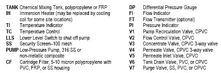
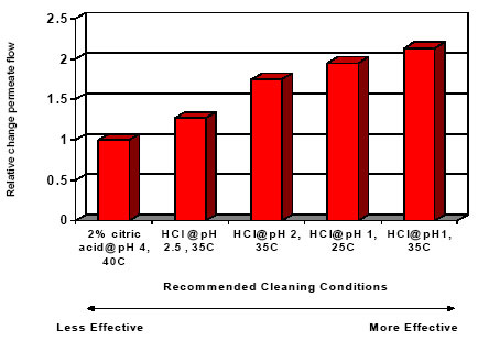
Figure 1 and 2 below show the importance of the selecting the right pH for successful cleaning.
Figure 1. Effect of pH on the removal of calcium carbonate
Calcium carbonate is best removed by cleaning with hydrochloric acid at pH 1-2.
Figure 2. Effect of pH on the removal of biofouling
Biofouling is best removed by cleaning at pH 12
Cleaning Chemicals
Table 3 lists suitable cleaning chemicals. Acid cleaners and alkaline cleaners are the standard cleaning chemicals. The acid cleaners are used to remove inorganic precipitates including iron, while the alkaline cleaners are used to remove organic fouling including biological matter. Sulfuric acid should never used for cleaning because of the risk of calcium sulfate precipitation. Reverse osmosis permeate or deionized water should be used for the preparation of cleaning solutions.
Table 3. Simple cleaning solutions
Cleaner Foulant |
0.1% (W) NaOH and pH 12, 35°Cmax. or 1.0% (W) Na4EDTA and pH 12, 35°C max. |
0.1% (W) NaOH and pH 12, 35°C max. or 0.025% (W) Na-DSS and pH 12, 35°C max. |
0.2% (W) HCI, 25°C and pH 1 - 2 |
1.0% (W) Na2S2O4, 25°C and pH 5 |
0.5% (W) H3PO4 , 25 °C and pH 1 - 2 |
1.0% (W) NH2SO3H , 25°C and pH 3 - 4 |
| Inorganic Salts (for example, CaCO3) | Preferred | Alternative | Alternative | |||
| Sulfate Scales (CaSO4, BaSO4) | OK | Preferred | Alternative | Alternative | ||
| Inorganic Colloids (silt) | Preferred | |||||
| Silica | Alternative | Preferred | ||||
| Biofilms | Alternative | Preferred | ||||
| Organic | Alternative | Preferred |
The temperatures and pH listed in table 3 are applicable for BW30, BW30LE, LE, XLE, TW30, TW30HP, SW30HR, SW30HR LE , SW30XLE, SW30 and NF90 membrane elements. For more information regarding the allowed temperatures and pH for cleaning, please refer to table 1.
Notes:
- (W) denotes weight percent of active ingredient.
- Foulant chemical symbols in order used: CaCO3 is calcium carbonate; CaSO4 is calcium sulfate; BaSO4 is barium sulfate.
- Cleaning chemical symbols in order used: NaOH is sodium hydroxide; Na4EDTA is the tetra-sodium salt of ethylene diamine tetraacetic acid and is available from The Dow Chemical Company under the trademark VERSENE* 100 and VERSENE 220 crystals; Na-DSS is sodium salt of dodecylsulfate; Sodium Laurel Sulfate; HCI is hydrochloric acid (Muratic Acid); H3PO4 is phosphoric acid; NH2SO3H is sulfamic acid; Na2S2O4 is sodium hydrosulfite.
- For effective sulfate scale cleaning, the condition must be caught and treated early. Adding NaCl to the cleaning solution of NaOH and Na4EDTA may help as sulfate solubility increases with increasing salinity. Successful cleaning of sulfate scales older than 1 week is doubtful.
- Citric Acid is another cleaning alternative for metal oxides and calcium carbonate scale. It is less effective (see also figure 1 of this document). It may contribute to biofouling especially when it is not properly rinsed out.